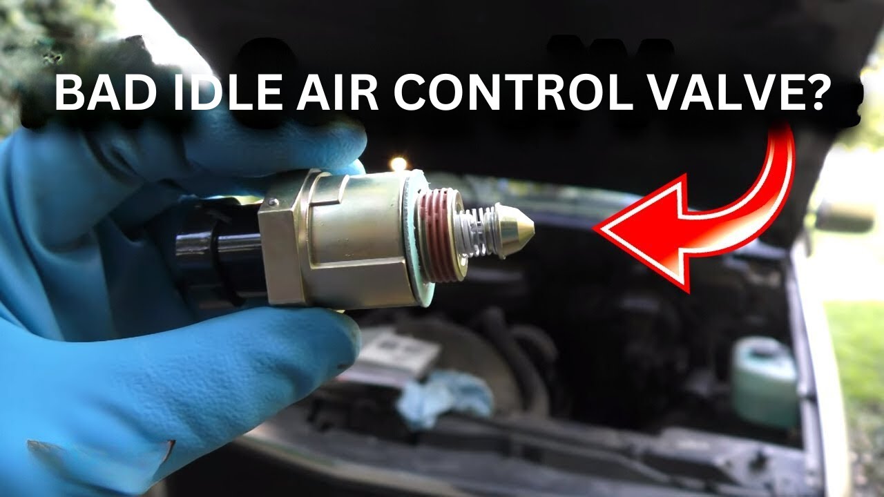
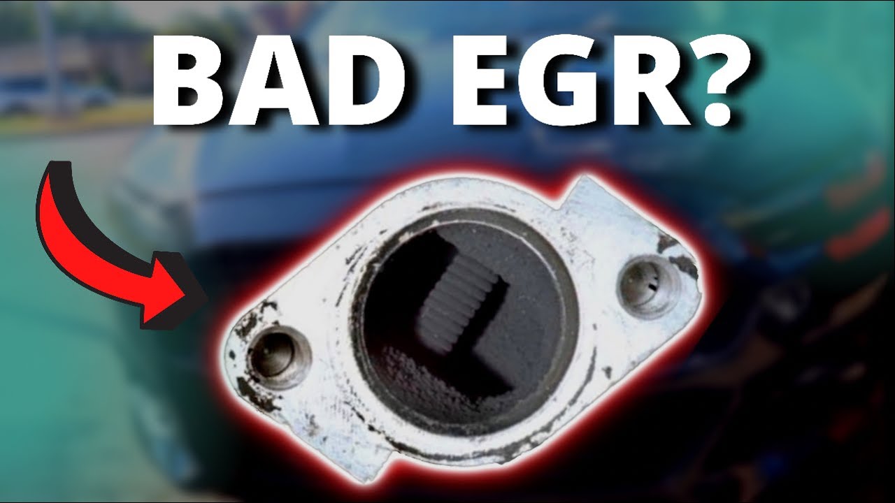
An idle air control valve is crucial for engine speed management. Unfortunately, carbon buildup can cover and diminish this component’s effectiveness. For maximum performance, clean or replace the component.
To clean engine parts, remove them from others. Mechanics and car owners often prefer immediate replacement. Detaching and replacing the component will take time and money.
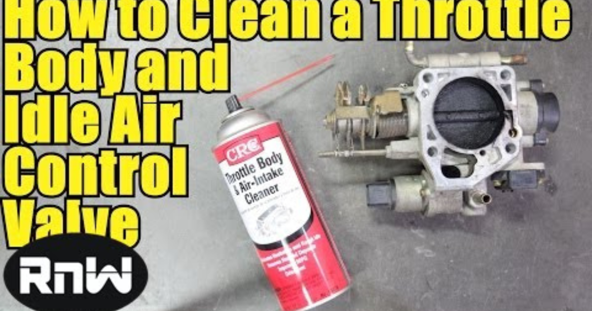
Cleaning an idle air control valve without removal saves money and time. Clean the idle air control valve using WD40. Rx Mechanic shows how to clean an idle air control valve without removing it. Sit down and read this page until the conclusion.
Step-by-Step Guide to Cleaning Idle Air Control Valve Without Removal

Protect yourself from chemicals and hot surfaces with gloves and goggles first.
Step 1: Set up your workspace
Though stupid, this is required. After a long trip, let the engine cool before cleaning. Be careful not to burn your hands. Before starting, put on gloves. Ideally, you can work before driving your baby ride that day.
Step 2: Locate the idle control valve
Find the idle air control valve before cleaning it. If you don’t know where your vehicle’s valve is, start at the air filter housing. The throttle body is connected to a huge black plastic air filter housing. The MAF sensor connects to the air filter box.
Follow the air filter box to the throttle body. The idle air control valve is commonly attached to the throttle body, depending on the automobile. Most automobiles have it underneath the throttle sensor.
Step 3: Disconnecting and removing the air ducts
Start by disconnecting the air filter box. Disconnect the filter and cover clamps. After that, disconnect the MAF sensor cable harness.
Find and disconnect all air duct-connected vacuum hoses.
Step 4: Disconnecting and removing the air ducts
Unscrew the clamp to separate and remove the throttle body air ducts. Place the screws in a safe cup and move the air duct to reach the idle air control valve.
Check the air filter for clogs before continuing. Clogged air filters reduce engine airflow, causing a harsh idle. It may explain the harsh idle. After cleaning the air filter, continue.
Step 5: find the IAC valve air passage.
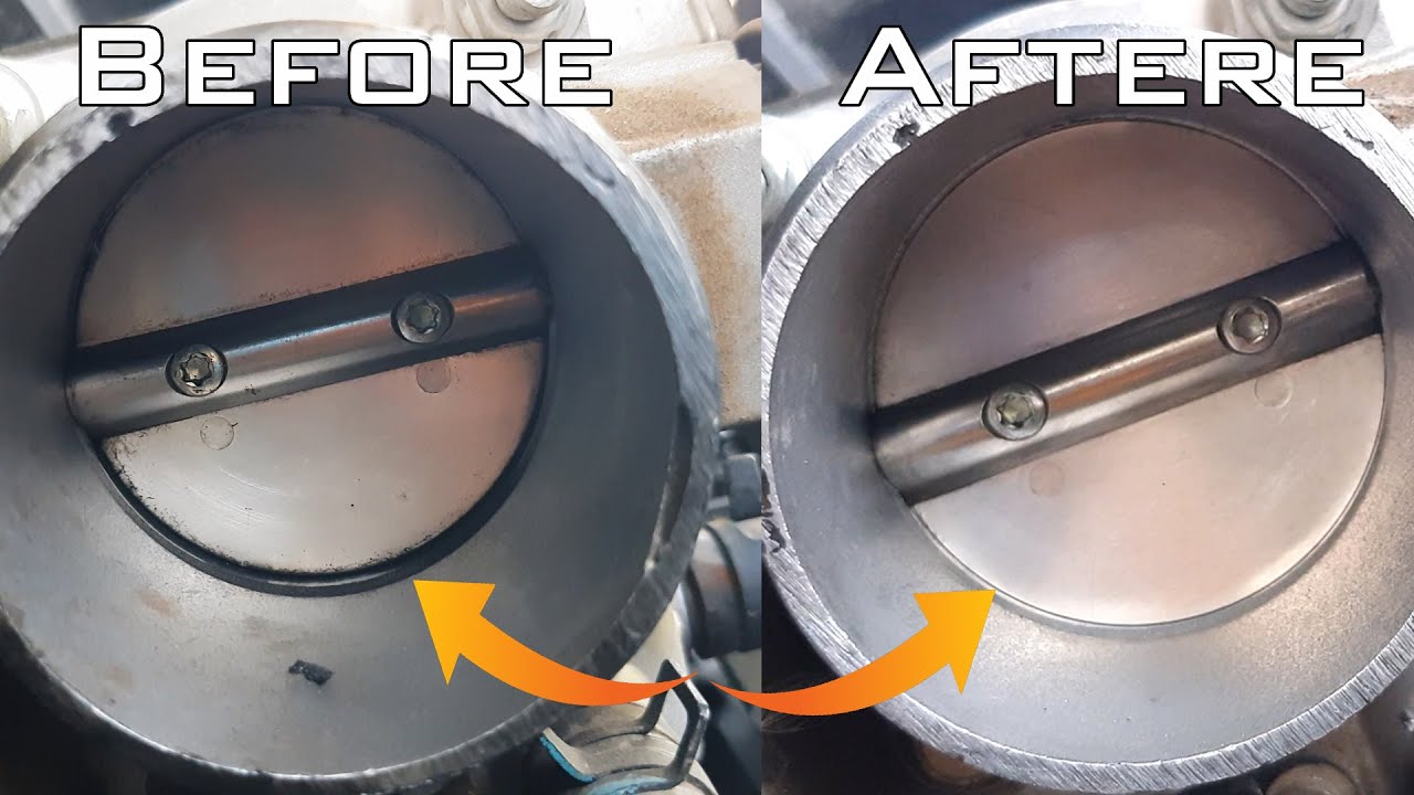
The throttle body has a small hole on the side. When the throttle body butterfly flang is closed, airflow enters the engine while idling. Check the little hole for carbon accumulation. That tiny hole will collect carbon, disrupting engine operation, especially at idle.
Step 6: Spray cleaning solution.
Use a throttle body or multi-purpose cleaner. Cleaning with WD40 is also excellent. Also needed is a little plastic brush to penetrate the hole. Please avoid metal wire brushes. It may mark the throttle body or ruin the channel.
Step 7: Finishing
After cleaning, reconnect all components. Do the reverse. Please reconnect and tighten the air duct screws on both sides. Connect the air filter housing and remove the hoses.
Multimeter Testing of an Idle Air Control Valve
If your idle air control valve is bad and you get error code P0505, don’t replace it right away. Problems may not originate there. You must verify the component’s badness before replacing it.
First, disconnect the electrical harness.
The idle air control valve wiring must be tested first. Unplug the wiring harness first. Get a multimeter. Check the wiring to make sure the idle air control valve is powered.
Second step: Ignite
Switch on the ignition. Do not start the car. Test the wiring harness connectors—usually six. Test no.2 and no.5 connectors. These are the middle up/down connectors.
Test the two connectors by grounding the black probe on a vehicle metal component. Expect about 12 volts. 11.6 and up is acceptable.
If you lose power, check for burned or frayed wires. A bad fuse may also be to blame. PCM malfunctions can cause it. Though unlikely, this happens.
Step 3: Unplug idle air control valve
Turn off the ignition and unplug the valve. Set your multimeter to ohms. Next, test ohms or resistance.
Step 4: Check resistance
These six connectors are three on top and three on bottom. Start by connecting the red lead to the central connector and the black probe to the other line connectors. Put the red probe in the middle and the black on the left connector. Change the black probe to the right connector.
Test the lower connectors after the top ones. All tests should be 30 ohms.

